1. Configuration Parameters
Test setup configured using short PUCCH Format 2 with Gold PRN sequence scrambling and QPSK modulation.
| Parameter | 3GPP Symbol | Value / Setting | Description |
|---|---|---|---|
| Channel / Format | — | PUCCH Format 2 | Short format (> 2 bits) with multiplexed DM-RS |
| RNTI | n_RNTI | 12345 | Radio Network Temporary Identifier for scrambling seed |
| Spreading Factor | N_SF | 1 | Spreading factor configuration |
| Interlace Allocation | — | Disabled | Contiguous physical resource block mapping |
| Allocated PRBs | N_PRB | 2 PRBs (24 subcarriers) | 16 data subcarriers, 8 DM-RS subcarriers |
| Allocated Symbols | N_symb | 1 Symbol | Short PUCCH symbol duration |
| Start PRB Index | n_PRB | 0 | Starting PRB index |
| First Symbol Index | S | 0 | First OFDM symbol index in slot |
| Modulation Scheme | — | QPSK (2 bits/symbol) | QPSK constellation mapping |
| Coded Bits | M_bit | 32 bits | 2 PRBs × 8 data subcarriers × 1 symbol × 2 bits |
| Slot Number | n_s,f^μ | 0 | Slot index within frame |
2. Expected Intermediate Values & DSP Execution
Intermediate output metrics from bit scrambling, QPSK constellation mapping, and subcarrier allocation.
Total Coded Input Bits:
Modulated QPSK Symbols (d_m):
Expanded Output Vector:
32 bits | Scrambled Bit Stream Size: 32 bitsModulated QPSK Symbols (d_m):
16 complex symbolsExpanded Output Vector:
48 complex elements (including OCC spreading factor)
| Stage | Element Count | Format / Domain | 3GPP Specification Reference |
|---|---|---|---|
| Scrambling (b_i) | 32 bits | Binary Vector {0, 1} | TS 38.211 Section 6.3.2.5.1 |
| Modulation (d_m) | 16 symbols | Complex QPSK Constellation | TS 38.211 Section 5.1.2 |
| OCC Sequence | 2 elements | (+1.000, -0.000) | Time-domain orthogonal sequence |
| Final Vector Grid | 48 elements | Complex Subcarrier Array | TS 38.211 Section 6.3.2.5.3 |
3. Subcarrier Multiplexing & Interlace Architecture
3GPP TS 38.211 subcarrier resource allocation mapping showing DM-RS pilots on indices k = 1, 4, 7, 10 alongside localized vs. interlaced PRB distributions.
Format 2 Subcarriers inside a single PRB (0 to 11):
+----+----+----+----+----+----+----+----+----+----+----+----+
| 0  | 1  | 2  | 3  | 4  | 5  | 6  | 7  | 8  | 9  | 10 | 11 |
+----+----+----+----+----+----+----+----+----+----+----+----+
|Data|DMRS|Data|Data|DMRS|Data|Data|DMRS|Data|Data|DMRS|Data|
+----+----+----+----+----+----+----+----+----+----+----+----+

Standard Localized PRBs (Contiguous):

[PRB 0][PRB 1][PRB 2][PRB 3] ... (Concentrated energy, bad for NR-U)

Interlaced PRBs for Interlace Index 0 (M = 5):
[PRB 0]------[PRB 5]------[PRB 10]------[PRB 15]------[PRB 20]...
^                                                               ^
+------------------- Spans > 80% of Bandwidth -----------------+

Subcarriers (Y-Axis)
^
|  [Symbol l=0, Seed A]   [Symbol l=1, Seed B]
| +--------------------+ +--------------------+
| |   Data Subcarrier  | |   Data Subcarrier  |
| |   Data Subcarrier  | |   Data Subcarrier  |
| |  PILOT (From PN A) | |  PILOT (From PN B) |  <-- Subcarrier index 1, 4, 7, 10
| |   Data Subcarrier  | |   Data Subcarrier  |
| |   Data Subcarrier  | |   Data Subcarrier  |
| |  PILOT (From PN A) | |  PILOT (From PN B) |
| +--------------------+ +--------------------+
+----------------------------------------------------> Time / Symbols (X-Axis)
4. Python Signal Analytics & Visualizations
Time-domain envelope and Power Spectral Density (PSD) plots exported from the Python test analytics pipeline.
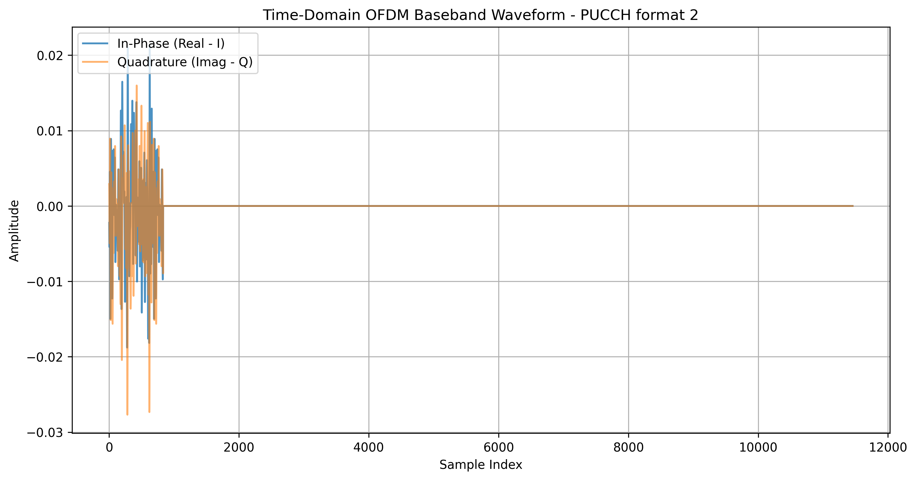
Figure 1: Time Domain Waveform
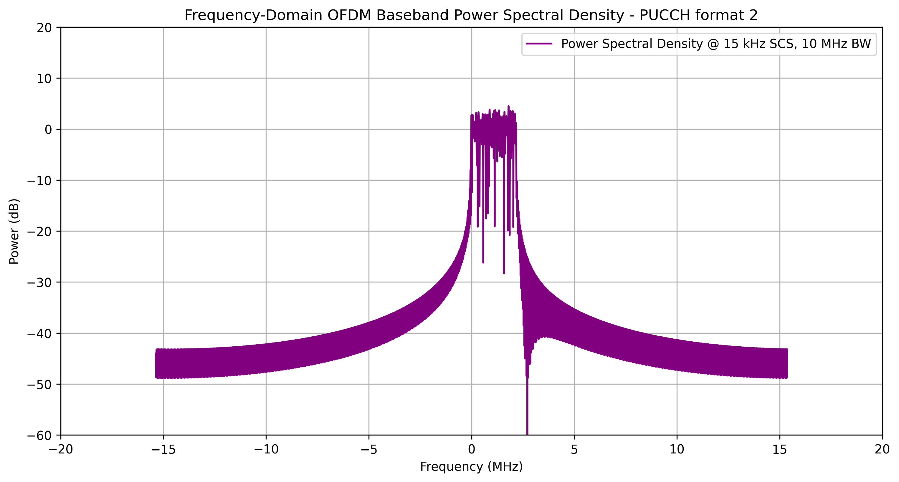
Figure 2: Power Spectral Density (PSD)