1. Configuration Parameters
Test setup configured for long PUCCH Format 3 with DFT-s-OFDM precoding and intra-slot frequency hopping.
| Parameter | 3GPP Symbol | Value / Setting | Description |
|---|---|---|---|
| Channel / Format | — | PUCCH Format 3 | DFT-s-OFDM long format (> 2 bits) without OCC |
| RNTI | n_RNTI | 12345 | Scrambling sequence seed parameter |
| Allocated PRBs | N_PRB | 2 PRBs (24 subcarriers) | Multi-PRB allocation (M_sc = 24) |
| Allocated Symbols | N_symb | 4 Symbols (l = 10 to 13) | Long PUCCH symbol allocation duration |
| Start Symbol Index | S | 10 | First OFDM symbol index in slot |
| Group Hopping | pucch-GroupHopping | Disabled (NEITHER) | Constant sequence group index (u = 10) |
| Frequency Hopping | intraSlotFrequencyHopping | Enabled (ISFH_ENABLE) | Intra-slot frequency hopping across 2 hops |
| Modulation Scheme | — | QPSK | QPSK constellation mapping |
| Cell ID | N_ID | 100 | Base sequence group index u = 100 mod 30 = 10 |
| Slot Number | n_s,f^μ | 0 | Slot index within radio frame |
2. Expected Intermediate Values & Symbol Multiplexing
Derivation of pilot vs data symbol allocations and frequency hopping indices across the 4-symbol slot allocation.
Total Allocated Symbols:
Data (UCI) Symbol Indices:
Pilot (DM-RS) Symbol Indices:
N_symb = 4 | Grid Dimensions: 24 subcarriers × 4 symbols = 96 elementsData (UCI) Symbol Indices:
{11, 13} (2 OFDM symbols)Pilot (DM-RS) Symbol Indices:
{10, 12} (2 OFDM symbols)
| Hop Index | OFDM Symbol Indices | Frequency Hopping Index | Sequence Group Index (u) | DM-RS Phase Shift (α) |
|---|---|---|---|---|
| Hop 0 | Symbol 10 (DM-RS), Symbol 11 (UCI) | 0 | u = 10 | α = 2.6180 rad |
| Hop 1 | Symbol 12 (DM-RS), Symbol 13 (UCI) | 1 | u = 10 | α = 4.7124 rad |
3. DFT-s-OFDM Precoding & Resource Grid Architecture
Resource grid mapping illustrating full-symbol DM-RS pilots and DFT-precoded UCI data symbols across 2 PRBs.
================================================================================
                    PUCCH FORMAT 3 RESOURCE GRID ARCHITECTURE
================================================================================

  Subcarriers (Y-Axis)
  M_sc = 24 (2 PRBs)
  ^
  |  +--------------------+--------------------+--------------------+--------------------+
  |  | DM-RS Symbol       | UCI Data Symbol    | DM-RS Symbol       | UCI Data Symbol    |
  |  | (Full PRBs)        | (DFT Precoded)     | (Full PRBs)        | (DFT Precoded)     |
  |  |                    |                    |                    |                    |
  |  | Low-PAPR Base      | Scrambled + QPSK   | Low-PAPR Base      | Scrambled + QPSK   |
  |  | Sequence r_u,v(n)  | + M_sc point DFT   | Sequence r_u,v(n)  | + M_sc point DFT   |
  |  +--------------------+--------------------+--------------------+--------------------+
  +--------------------------------------------------------------------------------------> Time (OFDM Symbols)
        Symbol l = 10        Symbol l = 11        Symbol l = 12        Symbol l = 13
        \____________________________________/    \____________________________________/
                   HOP 0 (startPRB)                          HOP 1 (secondHopPRB)

================================================================================
                         TRANSFORM PRECODING PIPELINE
================================================================================

  UCI Bits --> [ Scrambling ] --> [ QPSK Mod ] --> [ M_sc DFT Precode ] --> Grid REs

  Notes:      - No Time-Domain OCC (Allows higher spectral efficiency)
              - DM-RS occupies dedicated, un-multiplexed OFDM symbols
              - Low PAPR maintained via Transform Precoding (DFT-s-OFDM)
================================================================================
4. Python Signal Analytics & Visualizations
Time-domain envelope and Power Spectral Density (PSD) plots exported from the Python test analytics pipeline.
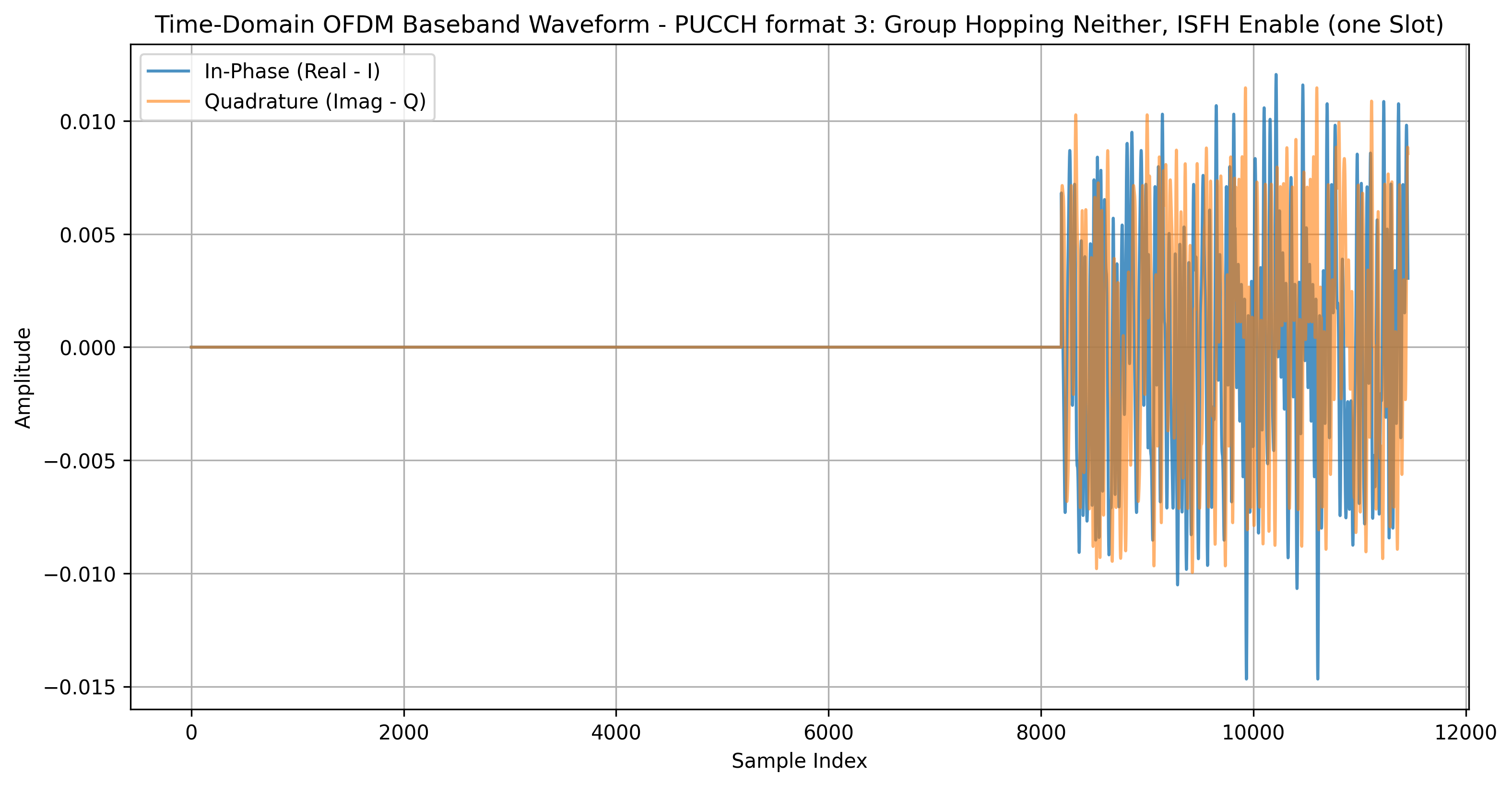
Figure 1: Time Domain Waveform
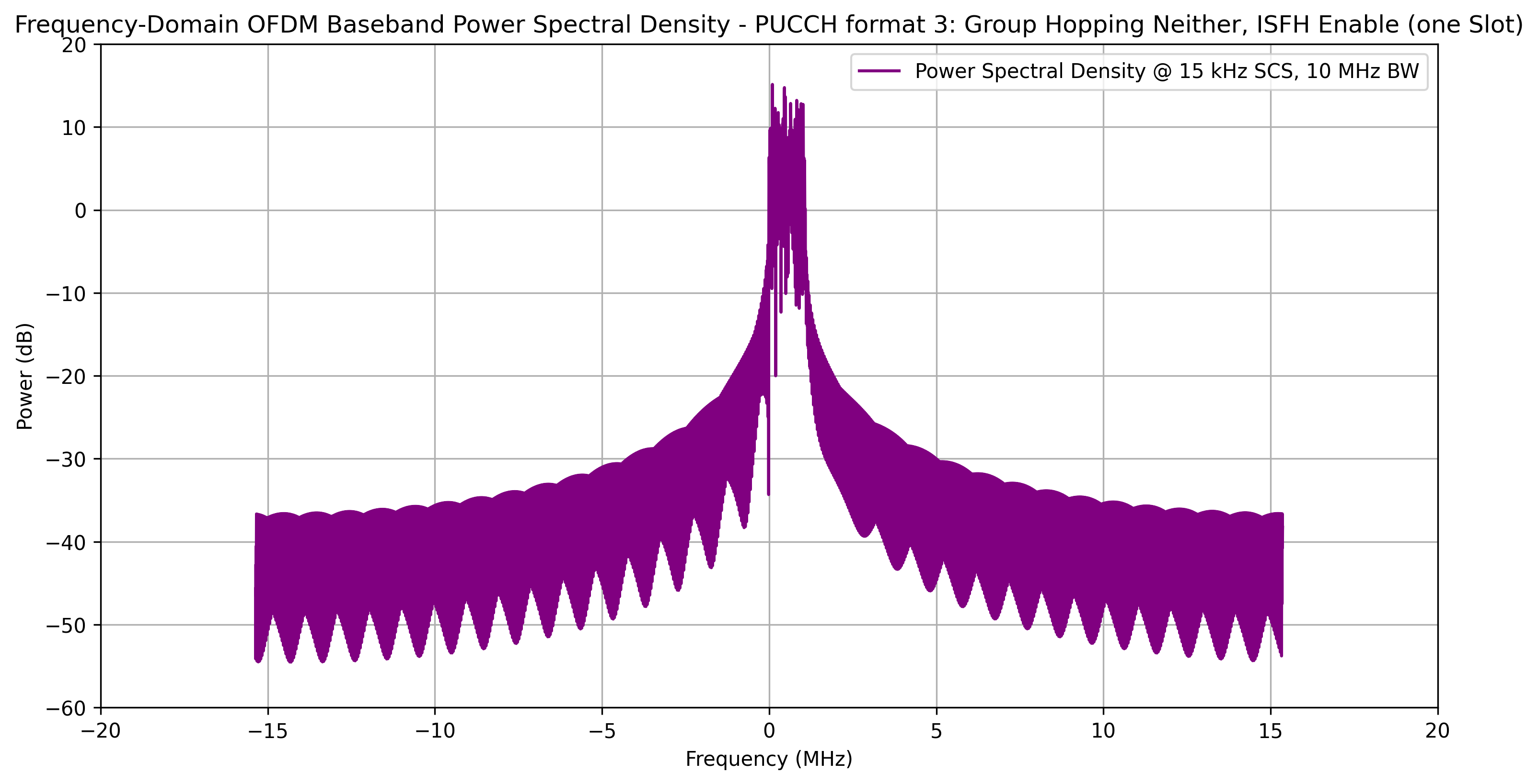
Figure 2: Power Spectral Density (PSD)